Temp. and Humidity Logger for the RPI4b
This is a simple temperature and humidity logger for a Raspberry Pi 4B running FreeBSD 14. It is capable of taking temperature and humidity every 5 seconds and storing them into a database. The measurements can then be viewed using either the integrated display, or, they can be exported to a USB drive.
Goals
One of the most important goals for this project is that this device should be low maintenance. Therefore, you should not have to connect it to a computer or the network for years at a time. As this device has not yet been in service for more than a few weeks, this cannot yet be guaranteed, however, it has been designed to, at least in theory, be capable of this. It allows you to change the device's time, date, and timezone from the built in display, as well as allowing you to export data and clear the internal storage of collected data. Finally, it should be able to survive a full drive, however, as there are a lot of variables, it may not be able to.
Contents
Construction
The following is a general list of materials required:
- 1x Raspberry Pi 4 Model B 1
- 1x Breadboard (medium or large)
- 4x Push button
- 1x DHT11/DHT22 2
- 1x DS3231 (or other RTC)
- 1x 16x2 HD44780U based LCD (such as a 1602 LCD, not I²C)
- 1x N-channel MOSFET (optional, for turning off the screen)
- 1x Schottky diode (optional, for turning off the screen)
- 1x 1kΩ resistor 3
- 2x 10kΩ potentiometers (optional, for display brightness and contrast control)
The following is one possible way to assemble the device. It should be noted, however, that all of the pins are configurable. Thus, the following design should be modified depending on the exact make and model of the parts being used.
If an I²C device will be used (such as the DS3231 or an I²C sensor), care must be taken that the data lines are connected to GPIO pins 2 and 3 (physical pins 3 and 5). If they are not, the configuration files provided in this repository will need to be updated to reflect the new I²C bus location. If multiple I²C devices are used, multiple busses will need to be created. For more information about I²C on FreeBSD see the following man pages: iic(4), iicbus(4), and fdt(4).
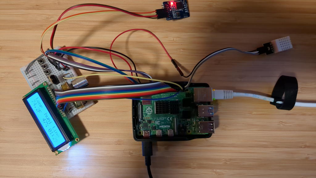
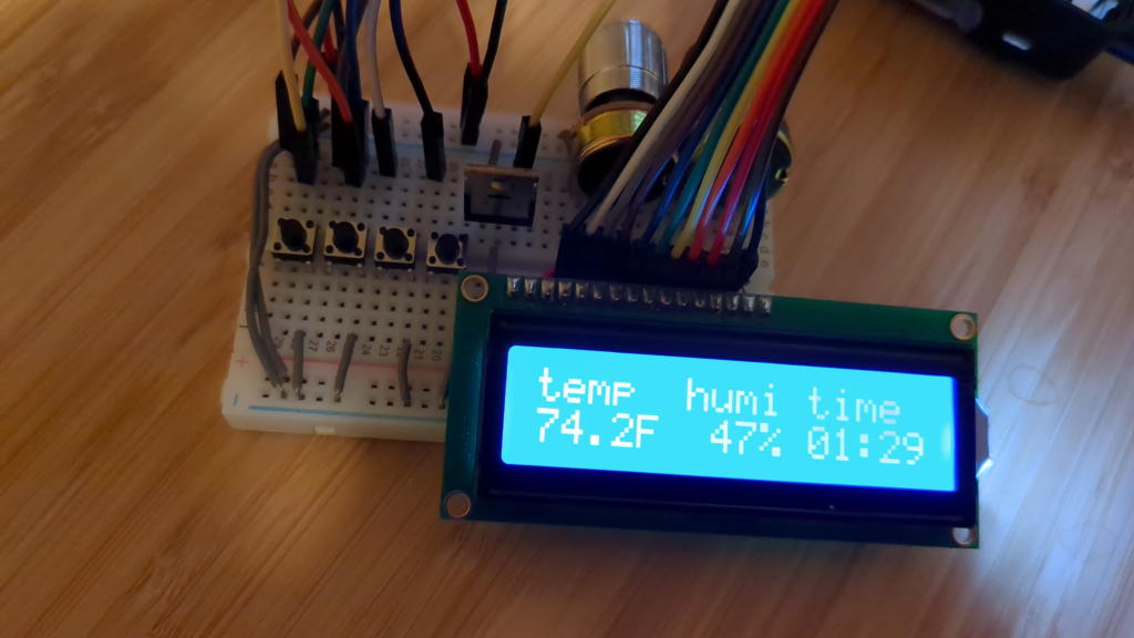
Some images of a fully assembled and working unit follow:
OS Preparation
This software was designed and tested on a system running FreeBSD 14.0. However, it should work on systems running FreeBSD 13 as well as on systems running future versions of FreeBSD. The FreeBSD installation process is very well documented in The FreeBSD Handbook. For convinience, the general procedure is also provided below. If any issues arise or you have any questions, be consult the handbook.
First, download the latest image for the Raspberry Pi here. It is also a
good idea to pick up the checksum file. Once done you should have two files with
names similar to FreeBSD-14.0-RELEASE-arm64-aarch64-RPI.img.xz and
CHECKSUM.SHA256-FreeBSD-14.0-RELEASE-arm64-aarch64-RPI. To verify the
downloaded files, open a terminal and execute the following commands (use sha512
if you downloaded the sha512 checksum file):
- GNU/Linux and FreeBSD:
sha256sum -c CHECKSUM.SHA256-FreeBSD-14.0-RELEASE-arm64-aarch64-RPI - OpenBSD:
sha256 -c CHECKSUM.SHA256-FreeBSD-14.0-RELEASE-arm64-aarch64-RPI
For other operating systems, please consult the relevant documentation.
Because device numbering is not persistent across boots, the export feature of
this software does not allow a specific device to be excluded from the
list. This may in the feature be rectified by an update, but for now, it is
recommend to install the OS to a microSD card. Most Raspberry Pis come with a
small USB device that can be used to write to microSD cards, as well as the
microSD card itself. If not, you can find both online very cheaply. Once you
have connected your device find it's device file using a tool like fdisk or
geom. Then execute the following commands as root to write the image to the
microSD card:
unxz FreeBSD-14.0-RELEASE-arm64-aarch64-RPI.img.xz
cp FreeBSD-14.0-RELEASE-arm64-aarch64-RPI.img /path/to/device
sync
If you are not comfortable with performing this operation on the terminal, another option is to use software such as balenaEtcher.
Once this process is done (which may take a while), insert the microSD card into the Raspberry Pi, attach a keyboard and monitor, and plug the Pi in to turn it on.
Installation
Once the system has booted and you see the login prompt, enter root as the
username and leave the password blank. You should now see a shell prompt. The first
thing to do is to configure the temperature sensor and the RTC. To do the
former, append the following to the end of the /boot/loader.conf file:
# Load the DHT11/DHT22 kernel module
gpioths_load="YES"
# The GPIO bus that manages the pins that the sensor is connected to
hint.gpioths.0.at=gpiobus0
# This number should have only the bit set for the position corresponding to the
# GPIO pin number that the sensor is connected to. For example:
# 2097152 -> 1000000000000000000000 -> pin 21 (bit 22)
# 1 -> 1 -> pin 0 (bit 1)
# 2 -> 10 -> pin 1 (bit 2)
hint.gpioths.0.pins=2097152

# Load the DS3231 kernel module
ds3231_load="YES"
# The I2C bus the controls the pins the sensor is connected to
hint.ds3231.0.at=iicbus0
# The *8 BIT* address of the sensor. The following is the default for a DS3231
# addr = 0xd0
hint.ds3231.0.addr=208
The FreeBSD base system comes with the text editor vi. For information about
how to use it, execute man vi or see vi(1).
The next step is to enable I²C for the DS3231. Once again, append the
following to the end of the [all] section of the /boot/msdos/config.txt
file:
# Set the initial state of pins GPIO 2 and 3. Change this if you use different pins.
gpio=2,3=a0
# Load the overlay for an the DS3231 I2C real-time clock
dtoverlay=i2c-rtc,ds3231
For example, the /boot/msdos/config.txt file on my Raspberry Pi 4B looks like
this:
[all]
arm_64bit=1
dtparam=audio=on,i2c_arm=on,spi=on
dtoverlay=mmc
dtoverlay=disable-bt
device_tree_address=0x4000
kernel=u-boot.bin
gpio=2,3=a0
dtoverlay=i2c-rtc,ds3231

[pi4]
hdmi_safe=1
armstub=armstub8-gic.bin
enable_uart=1
Then enable the ntpd and ntpdate services to sync with the RTC on boot and
periodically:
service ntpd enable
service ntpdate enable
If you want, you can also change the root password at this point:
passwd
After doing this, reboot the system. Once done, execute the following commands:
sysctl dev.ds3231.0.temperature dev.gpioths.0.temperature
If you get a warning about an unknown oid, it means that the sensor is not installed or configured correctly.
It should be noted that FreeBSD does not currently support wireless on the Raspberry Pi 4 at the time of writing. Thus, you will need to use a wired connection (or consult the handbook for information about other ways to get packages).
Once the sensors are detected and we have internet, we can install the dependencies for this software. Execute the following command to bootstrap the binary package manager pkg(7) and install sqlite3 and curl.
pkg install sqlite3 curl
When prompted to install pkg, type y and then press enter.
We can now download the source of this software:
cd /tmp
curl -O "https://git.zander.im/Zander671/rpi4b-temp-humidity/archive/main.tar.gz"
tar xf main.tar.gz
cd rpi4b-temp-humidity
At this point, take a moment to edit the config.mk file to to change any
default options. These can also be changed after installation by editing
/usr/local/etc/rpi4b-temp-humidity/config.conf.
Once you have configured everything to your liking, execute the following command to build and install the software.
make install
Configuration
The final step is to configure the software via the
/usr/local/etc/rpi4b-temp-humidity/config.conf file. Once you have done this
to your liking, execute the following command to enable the software on boot:
# Optional, set an alternate config file path
sysrc rpi4b_temp_humidity_config_file="/path/to/your/config/file"
service rpi4b-temp-humidity enable
The following command line flags are supported:
-h: print a simple help message, then exit-v: enable more verbose output-s: exit immediately if an error is found in the config file-f: specify a different config file path
These can also be modified via the following rc.conf(5) variables (or via the sysrc(8) command).
rpi4b_temp_humidity_config_file: same as-frpi4b_temp_humidity_strict_config: same as-srpi4b_temp_humidity_verbose: same as-vrpi4b_temp_humidity_log_file: file to write output to, set to empty to discard output
Usage
The buttons from closest to the display to farthest are: select, back, up, and down. When the device first turns on, the stats screen will be shown. This screen displays the current temperature, humidity, and time. Pressing the back button will take you to the main menu. The following is a short description of each screen:
- "Stats by" screen shows stats by a specific period (e.g. hour, day, week)
-
Other versions and models will very likely work (such as the Pi 3B), the wiring will just need to be adjusted. ↩︎
-
Any temperature and humidity sensor for which a FreeBSD kernel module exists will work. You can even use separate sensors for each! ↩︎
-
If your DHT11/DHT22 is mounted on a carrier board with only three terminals, it likely already has this resistor. When in doubt, check the data sheet. ↩︎


